
- Two timers, programmable for up to ten hours, each working independent of each other, and independent of oven cook operations.
- A clock, displaying the current time of day.
- A "Delay Cook" operation, which enables programmed cooking to be done at a later time, programmable up to 24 hours in advance.
- Wi-Fi connectivity, allowing the user to modify cooking programs from anywhere with internet access.
- Eight ringtones, which can be individually chosen for each of four oven operations.
- Individual control of both burners for cooking programs.
Operating Instructions
Main Menu
Cook Programming Mode
Ringtone Menu
Wi-Fi
Block Diagram
Description
Schematic
Circuit Operation
Software Function
Ringtone Programming
Audio Samples
The Main Menu consists of six parts, five of which can be accessed and manipulated.

- Cook - shows information about the current status of the toaster's cooking program. One of five things may be displayed:
- "Cook" - this will display when no program is set. SELECTing this will enter "Cook Programming Mode".
- Remaining cooking time - If cooking is in progress, the remaining time will display. If the time remaining is over one hour, the time will display in h:mm format. If the time is under one hour, the time will be displayed in mm:ss format. Pressing SELECT while in this mode will bring up an option to "Clear" the program. Pressing SELECT again will clear the current program and return the oven to the Main Menu where "Cook" will again be displayed. Pressing any other key will return to the Main Menu leaving the current program intact. When cooking time has expired, an alarm will sound and the cooking program will be cleared.
- "PreHt" - this will display if the oven is in preheat mode. Pressing SELECT while in this mode will bring up an option to "Clear" the program. Pressing select again will clear the current program and return to the Main Menu where "Cook" will again be displayed. Pressing any other button will return to the Main Menu leaving the current program intact.
- "Ready" - When preheating has finished, the word "Ready" will appear on the main menu and an alarm will sound. The word "Ready" will remain and the oven will be kept at the selected temperature, during which time the alarm will sound once per minute until SELECT is pressed or until ten minutes pass. When SELECT is pressed, the cook timer will begin running and the remaining cooking time will be displayed. If SELECT is not pressed within ten minutes, the program will be cleared and "Cook" will again display.
- Delay start time - If a future program has been set, the start time of the program will be displayed. The start time will reflect the end time of the program minus the cooking time. When SELECT is pressed in this mode, an option will be presented to "Clear" or to "View/Change" the program. Selecting "Clear" will clear the current program and return the oven to the Main Menu where "Cook" will again be displayed. Selecting "View/Change" will enter "Cook Programming Mode", where the currently selected program may be viewed or modified.
- Temperature - the Main Menu will continuously show the current temperature inside the oven, rounded to the nearest 5 degrees Fahrenheit.
- Clock - when selected, the system clock can be set or changed. Time is displayed in 24 hour hh:mm format. When no time is set, "Clock" will display on the Main Menu.
- Time1 and Time2 - when these timers are inactive, "Time1" or "Time2" will display. Pressing SELECT will bring up a timer, which will be displayed in h:mm:ss format and may be programmed for up to ten hours. When the timer is active, the remaining time will display. If over one hour remains, the time will display in h:mm format. If under one hour remains, the time will display in mm:ss format. When each timer expires a customizable alarm will sound.
- Ring - when selected, a ringtone may be selected for any of four oven functions. "Cook" selects the alarm to sound when cooking is finished. "Ready" selects the alarm to sound when preheating has finished and the oven is ready to cook. "Time1" and "Time2" select the alarms to sound when Timer 1 and Timer 2 have respectively expired. When either of these is selected, the "Ringtone" menu will be displayed.
- "Cook Now" or "Cook Later" - when "Cook Now" is selected, options will be presented for "Burner", "Temperature", and "Cook Time". When "Cook Later" is selected, options will be presented for "End Time", "Burner", "Temperature", and "Cook Time".
- "End Time" (Cook Later Only) - end time for the Delay Cook feature can be set. Time is displayed in 24 hour hh:mm format.
- "Burner" - Three options may be selected:
- "Both Burners" - Both the upper and lower burners will be used in preheating and cooking operations.
- "Upper Only" - The upper burner will be used primarily in cooking operation. Note that both burners will still be used for preheating in order to bring the oven up to operating temperature as quickly as possible. Also, for temperatures above 325° one burner is insufficient to adequately heat the oven. For these temperatures, the upper burner will remain constantly on while the lower burner will cycle on and off to maintain the desired temperature.
- "Lower Only" - The lower burner will be used primarily in cooking operation. Note that both burners will still be used for preheating in order to bring the oven up to operating temperature as quickly as possible. Also, for temperatures above 325° one burner is insufficient to adequately heat the oven. For these temperatures, the lower burner will remain constantly on while the upper burner will cycle on and off to maintain the desired temperature.
- "Temperature" - One of eleven cooking temperatures may be selected, ranging from 200° to 450° Fahrenheit in 25° increments.
- "Cook Time" - The desired cooking time may be entered. Time will be displayed in h:mm:ss format and may be programmed for up to ten hours.
The Ringtone Menu allows selecting from eight preset ringtones. Default is set to "Single Beep". When accessing the Ringtone Menu this will play. Pressing DOWN will toggle through "Simple Beep", "2001 1", "2001 2", "2001 3", "Frequency Increase", "Simpsons", and "Billie Jean", playing each one in turn. Pressing UP will toggle through the same ringtones in reverse. To select a given ringtone, simply press SELECT when it finishes playing.
The toaster oven will automatically connect to a configured Wi-Fi network. Once connected, a scheduled cook program may be modified or cleared from anywhere with internet access. To do so, run the "Toaster Oven" application and follow these steps:
- When the program is started, a button will display which reads "Get Program". Click this button to retrieve current program information.
- If no program is set, "No Program Set" will display.
- If a program is set, the current end time will display, followed by an option to "Clear" the current program, and an option to "Change" the current program. To clear, simply choose "Y" from the drop down menu and click on "Submit".
- To change, choose the new end time from the drop down menus and click "Submit". The new end time will appear, confirming that the request has been received by the toaster oven.
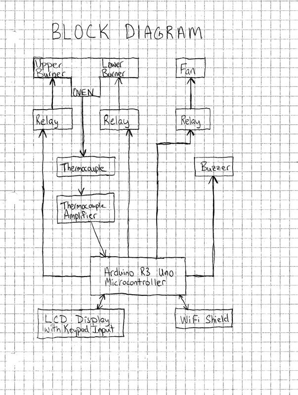
All functions of the toaster oven are controlled by the Arduino microcontroller.
The microcontroller constantly communicates with the LCD Keypad to display current information and to receive keypad input from the user.
A thermocouple is mounted in the oven. The voltage this reads gets amplified by the amplifier, and is read in by the microcontroller.
The microcontroller uses this information to display the current temperature, to turn on and off two relays which control the two burners inside of the oven, and to turn on and off a relay which controls the fan.
The microcontroller sends a signal to the buzzer to play ringtones whenever an alarm is activated.
The Wi-Fi shield connects to the internet, which allows the user to modify certain program settings. The program used to make these modifications is a client-side html, which is served by the microcontroller through the Wi-Fi shield.
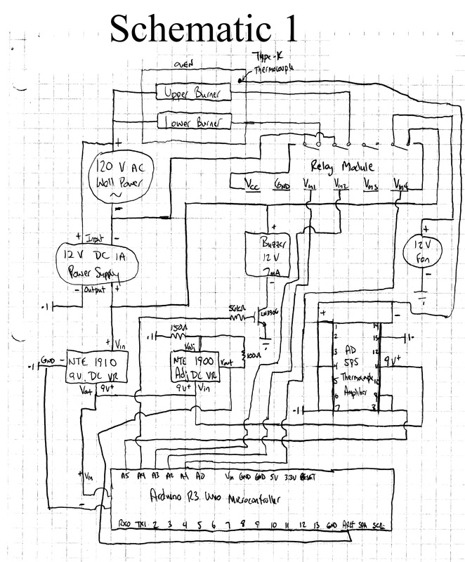
Power to the entire system is supplied by 120V AC wall power with two leads. This signal is split three ways.
Two of the wires from this split from one of these leads connect to the upper and lower burners in the oven, which then run through relay 2 and relay 1 respectively, and back to the other lead of the wall power. Relay 1 and relay 2 are controlled by the digital output on pins A2 and A3 on the microcontroller, respectively.
The third wire from the split of one of these leads connects to one terminal of a 12V DC 1A power supply. The other terminal of this power supply connects back to the other lead of the wall power. This power supply powers the rest of the system.
The 12V power then splits three ways. The first lead powers the 12V fan through relay 4, which is controlled by digital output on pin A1 on the microcontroller.
The second lead powers the buzzer. It connects to the positive terminal of the buzzer, which operates best at ~12V and 7mA. The negative terminal of the buzzer then runs to the emitter of the BJT transistor. The collector of the transistor connects to ground. The base of the transistor is controlled by digital output on pin A4 on the microcontroller through a 56kΩ resistor to supply ~70uA. The transistor has a Beta value of about 100, which allows ~7mA to flow through the buzzer.
The third lead from the 12V power supply powers a fixed 9V voltage regulator, which powers the rest of the system. The 9V regulator is used to nullify the effects that the fan and buzzer have on the rest of the system when turning off and on.
The 9V power then splits three ways. The first lead powers the microcontroller.
The second lead powers the amplifier for the thermocouple.
The third lead powers an adjustable voltage regulator. A 100Ω resistor is connected from Vout to Vadj on this regulator, and a 150Ω resistor is connected from Vadj to ground, which supplies ~3.1V to the AREF pin on the microcontroller.
The hot junction of the thermocouple is mounted inside the oven. The cold junction positive lead connects to pin 1 on the thermocouple amplifier, and the negative lead connects to pin 14. Pins 1, 4, and 7 of the amplifier are grounded. Pins 8 and 9 are connected together, and run to analog input pin A5 on the microcontroller. The amplifier provides ~10mV/°C output to the microcontroller. Using the default analog reference of 5V would allow readings up to ~500°C: well above 232°C, the maximum operating temperature of the oven. Because the microcontroller reads 1,024 values for analog input, supplying 3.1V to the AREF pin allows greater precision when reading temperature values.
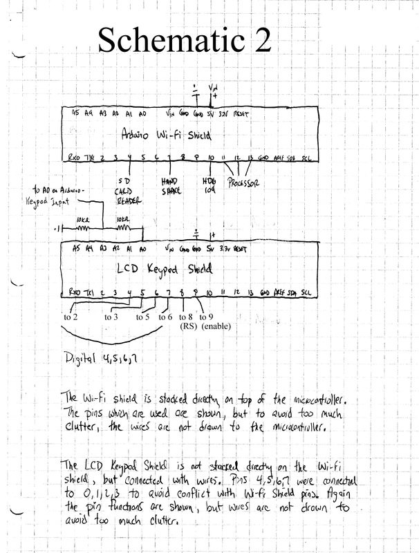
The Wi-Fi shield stacks directly on top of the microcontroller. Pins 4, 7, 10, 11, 12, and 13 are used for communication between these two devices, and so cannot be used by other devices.
The microcontroller uses pins RX0 and TX1 for Serial communication. These pins cannot be used by other devices when Serial communication is desired
The LCD Keypad uses pins 4, 5, 6, 7, 8, and 9 to communicate with the microcontroller. To avoid pin conflicts with the Wi-Fi shield and Serial communication, these are connected to pins 2, 3, 5, 6, 8, and 9 on the microcontroller, respectively. In the code, the LCD Keypad constructor was modified accordingly. The LCD Keypad uses a 5-stage voltage divider to communicate keypad presses to the microcontroller on analog input pin A0. However, the voltages which it outputs are in reference to 5V. Because the AREF of the microcontroller was changed to ~3.1V, a simple voltage divider using two 10kΩ resistors is used between the Keypad output and microcontroller input. This supplies voltages within range of the reference input voltage, but with slightly lower input values than the Keypad library is written for. In the code, the LCD Keypad reference values were adjusted to compensate.
This is a very rough outline of how the different pieces of code operate and work together.
- Main Program
- Contains Objects:
- LCDKeypad
- Cook
- Clock
- Timer1 (type Timer)
- Timer2 (type Timer)
- MusicScale
- Program Flow
- Setup:
- Connect to Wi-Fi
- Create Objects
- Loop:
- Check for button press from Keypad:
- If UP, DOWN, LEFT, or RIGHT -> move cursor accordingly
- If SELECT:
- If cursor in Cook position:
- If Cook is ready, run Cook Timer
- Else -> Set Cook Options
- If cursor in Clock position -> Set Clock
- If cursor in either Timer position:
- If Timer not set -> Set Timer
- Else -> ask to clear Timer
- If cursor in Ring position -> Set Ring
- If cursor in Cook position:
- Once each second (i.e. Current Time != Previous Time):
- Check for Connected Wi-Fi Client, if Yes:
- Read Input
- Make changes to Cook program if needed
- Send HTML code back with updated information
- Calculate average temperature reading from last second
- Turn Fan on or off depending on temperature
- Print temperature to LCD Display
- Update Clock, Update Cook, Update Timers
- Check for Connected Wi-Fi Client, if Yes:
- Increment Temperature Counter, Increment Temperature Reading Total
- Check for button press from Keypad:
- Set Ring:
- Check for button press from Keypad:
- If UP, DOWN, LEFT, or RIGHT -> move cursor accordingly
- If SELECT -> Set Ringtone
- Check for button press from Keypad:
- Set Ringtone:
- Play tune
- Check for button press from Keypad:
- If UP or DOWN -> Play new tune
- If SELECT -> Set appropriate object's Ringtone
- Setup:
- Clock Class
- Important Functions:
- Set Time:
- Sets the current time inputted by user
- Update:
- Prints current clock time to LCD Display
- Set Time:
- Cook Class
- Contains Objects:
- Clock
- Timer
- MusicScale
- Important Functions:
- Set:
- If Cook Later -> Set Clock Time
- Set Burner Selection
- Set Temperature
- Set Timer
- Update:
- If Timer is running -> Update Timer
- If Timer done running -> Play Music Scale and Clear
- If Ready:
- If one minute passed since last -> Play Music Scale
- If ten minutes passed -> Clear
- If Timer Set but Not Ready -> Preheat
- If Temperature < Threshold -> Turn Burner(s) on
- If Temperature > Threshold -> Turn Burner(s) off
- Set:
- Contains Objects:
- MusicScale Class
- Important Functions:
- PlayTune (selectTune) -> Plays selected preprogrammed tune
- Play (duration) -> Plays a rest of specified duration
- Play (note, duration) -> Plays a note for the specified duration
- Play (note, note, duration) -> Plays a chord of two notes for specified duration
- Play (note, note, note, duration) -> Plays a chord of three notes for specified duration
- Timer Class
- Contains Objects:
- MusicScale
- Important Functions:
- Set:
- Sets the Timer time inputted by user
- Update:
- Adjust Time Remaining
- If Time Remaining < 0 -> Play Ringtone
- Set:
In music, as you may know, the pitch of a sound that we hear is a result of its frequency. The human ear is able to detect from about 20 to 20,000 vibrations per second, or Hertz (Hz). Concert A, for example is defined as 440 Hz. Any sound that is repeated or vibrates at 440 cycles per second will sound like an A. When I bought the buzzer that was used in this project, I had initially intended to simply use it to beep when an alarm needed to be sounded. However, once I had it hooked up, I decided to have some fun with it.
To have the buzzer play concert A, it would be necessary to turn it on and off 440 times per second. This would correspond to a cycle time of 1/440 = 0.0022727s, or 2.27ms or 2,273us. So if I had the buzzer cycle through a loop, turning on for half the cycle time, followed by off for half the cycle time, it should play an A. I wrote some simple code to test this, something like:
#define A 440; // so I can use A instead of having to type in 440 each time
#define BUZZER A5; // A5 was the pin I was using to control the buzzer on the microcontroller
for (int i=0; i<A; i++) {
digitalWrite (BUZZER, HIGH);
delayMicroseconds (1000000 / A / 2); // turn the buzzer on for 1/2 cycle
digitalWrite (BUZZER, LOW);
delayMicroseconds (1000000 / A / 2); // turn the buzzer off for 1/2 cycle
}
In theory this should have produced an A for a duration of 1 second, and for all my tone-deaf ear knew it did, except that it sounded a little muddy. It occurred to me that because the buzzer makes a distinct pitch by itself when it is turned on, I may be hearing that pitch resonating along with the pitch of the "A". To minimize this effect, I reduced the amount of time the buzzer was on during each cycle:
for (int i=0; i<A; i++) {
digitalWrite (BUZZER, HIGH);
delayMicroseconds (10); // turn the buzzer on for 10us
digitalWrite (BUZZER, LOW);
delayMicroseconds (1000000 / A - 10); // turn the buzzer off for the remainder of the cycle
}
This indeed worked much better. I next tried to play an octave of a major scale, starting on C at 262 Hz and ending on C at 523 Hz, using code similar to above for each note. It sounded okay, but even my inept ear could tell that it wasn't quite right. I looked online for assistance, but all posts about controlling pitch using an Arduino microcontroller yielded results which were similar to what I had just done.
Then something occurred to me. In theory, based on the delay times, each cycle of the above code should take 1/440 of a second to execute, but this completely neglects the amount of time for each line of code to execute. Executing each command (for, digitalWrite, delayMicroseconds) may take time which is significant compared to the cycle time. I tested this by holding the note out for what theoretically should have been 30 seconds, measuring the start time and end time. Indeed the time elapsed was closer to 31 seconds than 30. So I adjusted the cycle time by raising the "frequency" of A. I did so until I had a value which resulted in the note being held out for almost exactly 30 seconds (30.008s). The new frequency wound up being 452Hz instead of 440Hz. I then repeated this procedure for each note in my octave (and later for each note in a two octave range). I was now able to play a major scale which sounded perfect!
Note: for reference for anyone who may wish to make music with an Arduino Rev3 Uno, here are the results:
| Note | C | C# | D | D# | E | F | F# | G | G# | A | A# | B | C | C# | D | D# | E | F | F# | G | G# | A | A# | B | C |
| Theoretical Frequency | 262 | 277 | 294 | 311 | 330 | 349 | 370 | 392 | 415 | 440 | 466 | 494 | 523 | 554 | 587 | 622 | 659 | 698 | 740 | 784 | 831 | 880 | 932 | 988 | 1047 |
| Adjusted Frequency | 267 | 283 | 300 | 318 | 337 | 357 | 379 | 402 | 426 | 452 | 480 | 509 | 540 | 573 | 608 | 645 | 685 | 727 | 772 | 820 | 870 | 924 | 982 | 1043 | 1108 |
I next decided to try to see if I could get the buzzer to play some chords. I knew that it would be impossible to have the buzzer simultaneously play two or three notes, but if the notes could be quickly arpeggiated, it may create the illusion of simultaneity. I programmed the buzzer to play a C for 10 cycles, followed by an E for 10 cycles, followed by a G for 10 cycles. The result sounded like a chord, but the arpeggiation was clearly noticeable. I reduced the number of cycles until it sounded reasonably like a chord, which occurred at about 4 cycles. The result was still slightly less than ideal, but passed well enough for a chord. My musical genius brother then suggested that perhaps the chord sounded off because 4 cycles would equate to different lengths of time for different notes. For example, within the same octave, 4 cycles of a G would take 1 1/2 times as long to complete as 4 cycles of a C. I was planning on using 3-note chords with a 1, 5, 10 positioning, so I wrote code that had the root cycle 4 times, the fifth cycle 6 times, and the third (up an octave) cycle 10 times, so that each note would have approximately equal duration. The result (in my opinion) was quite good.
One last thing I wanted to try with the buzzer was to gradually increase its frequency. This would illustrate a couple of things. First, if the frequency started below 20Hz, the transition from a pulse to a pitch should be able to be heard. Second, as the frequency increased from 20Hz to 20kHz, the pitch should rise from the low end of the audible range to the high end of the audible range. In my opinion the result of this was quite good as well.
Single Beep
Simple Beep
2001 1
2001 2
2001 3
Frequency Increase
Simpsons
Billie Jean